")
")
")

")
Lodestar FM-CS
{phocadownload view=file|id=16|text=Leaflet. Feeder Monitor Lodestar FM-CS - DOWNLOAD|target=s}
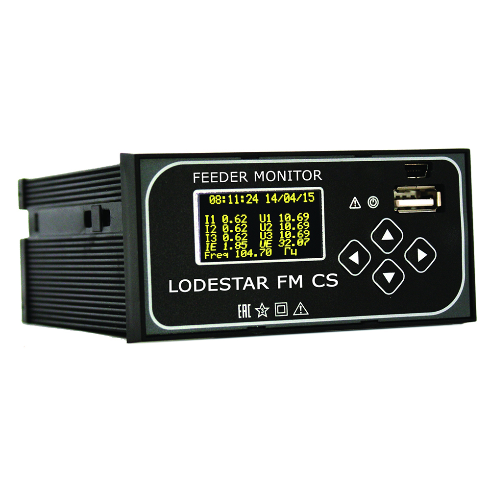
Lodestar FM-CS is a universal device for registration and analysis of fault processes in a network of any topology and neutral type. Lodestar FM-CS can be used as a logger, fault current indicator, high-voltage control device. It could be installed on the control board of relay compartment of a switchgear of any type on panels and control cabinets of relay equipment and on control boards of the substation.
The functionality of model Lodestar FM-CS is similar to model Lodestar FM, but it also has own easily mounted current sensors based on Rogowski coil that gives the following advantages:
• Current transformer does not have unnecessary load;
• It does not cause distortion when using a current transformer for measurements;
• It is used in substations where regular current transformers are not planned, installed or required.
Lodestar FM-CS model has:
• Different absolute and differentiated current thresholds;
• Other measurement accuracy;
• Communication protocol IEC 60870-5-104 is added.
Lodestar FM-CS benefits:
 |
Detects fault direction |  |
Effective in resonant grounded neutral grids |
 |
Logs all types of emergency situations: - phase-to-phase faults; - phase-to-ground faults; - 2-or-3-phase-to-ground faults |
 |
Operates in mixed systems: overhead, cable and overheadcable ones |
 |
High accuracy in measurement of current and voltage |  |
Above 0.1 A short circuit fault logging |
 |
Immediate data processing in the Device |  |
Operates in double-ended and loopfed grids, as well as in radial grids |
 |
Feeder Monitor Lodestar FM-CS displays a faulted phase on the front LED-display |  |
Event information both visually and in the SCADA system |
 |
Easy to configure by a couple of clicks in SW |  |
Memorizes more than 200 events |
Technical specifications
| PARAMETER | VALUE |
| Types of logged faults | - 2-and-3-phase short-circuit fault identification; - 2-and-3-phase short-circuit fault direction finding; - 2-and-3-phase-to-ground fault identification; - 2-and-3-phase-to-ground fault direction finding; - Phase-to-ground fault identification; - Phase-to-ground fault direction finding |
| Determining the directions of PtG | Yes |
| Logging the line switching faults | Yes |
| Selectivity | Phase-to-ground and short-cicuit faults direction finding (PtG, PtP) |
| Current response threshold PtG | from 0,5 A |
| Current response threshold PtP | from 10 A |
| Fault visual indication | - LED-display; - LED indication |
| Number of memorized faults | 240 |
| DEVICE GENERAL DESCRIPTION | |
| External measuring sensor | - Rogovsky coil (3 pcs.) - Standard / capacitive divider |
| Power supply used in the indicator | - Inbuilt standby removable lithium storage battery (15 years); - Powered via operation current source with any type of voltage =100 – 240 V (±10%) |
| Fault indication reset | - By an external command; - By the timer; - By the device button |
| Interface | RS-485 MODBUS communication protocol Ethernet IEC104 communication protocol |
| Logging of | - Voltage; - Current; - Power; - Industrial frequency; - Power factor in three phases; - Flow distribution direction; |
| Measurement accuracy | - Voltage: - when using capacitive dividers- 3%; - when using volatge transformer - 1%; - Current3%; - Active, reactive and full power 3%; - Industrial frequency 1% |