")
")
")

")
Lodestar FM-DFI
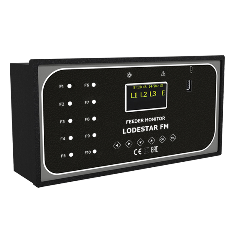
Lodestar FM-DFI is a universal device for registration and analysis of emergency processes that combines the functions of selective detection of line damage in networks of any topology and type of neutral and measurement of basic parameters of electricity. The Device is designed to detect the fact and determine the direction of phase-to-phase short-circuits, phase-to-ground fault in overhead and cable power distribution lines of 6-35 kV.
Lodestar FM-DFI is mounted in the switchgear and control gear cell of the control board. The Device can operate without reconfiguration in radial networks, as well as in open, closed loop networks, ring networks with power supply from both sides, with automatic or manual restoration of power supply. It operates without reconfiguration in networks with insulated and compensated neutral, and has the ability to work in a network with grounded neutral.
Lodestar FM-DFI monitors the minimum voltage and extra voltage with indication of alarm signals. Lodestar FM-DFI triggers and detects a fault when there are phase-to-phase and phase-to-ground faults in the monitored line accompanied by a sudden increase in current in the faulty phases, followed by a voltage drop in the line below the specified threshold, or without lowering the voltage, depending on the settings defined by the user.
Technical characteristics of Lodestar FM-DFI
| PARAMETER | VALUE |
| Types of registered faults | |
| Types of recorded faults | - 2- and 3-phase short circuits identification; - 2- and 3-phase short circuits direction detection; - 2- and 3-phase –to-ground fault identification; - 2- and 3-phase-to-ground fault directionidentification; - phase-to-ground fault identification; - Phase-to-ground fault direction detection |
| Recording the line switching faults | Yes |
| Selectivity | Detection of the direction of phase-to-ground and short circuit faults |
| Minimum zero sequence current for phase-to-ground fault registration | 0.5 A |
| General description of the devices | |
| Voltage class of overhead and cable power distribution lines | 6-35 kV |
| Network frequency | 45-65 Hz |
| Visual indication of the fault | - LCD indicator - LED indication |
| Number of last faults stored in the internal memory | 240 |
| Power supply used in the indicator | - Built-in standby extracted lithium battery (15 years) - Powered from: - an auxiliary services supply with any type ofvoltage = 110-240V (± 10%), - line supply ~100-270 V, - or constant voltage: 1) A= 9-18 V (nominal value of 12 V) 2) B=18-36 V (nominal value of 24 V) 3) C= 36-72 V (nominal value of 48 V) |
| Resetting the fault indication | - With the external command; - by the timer; - by the button on the Device |
| Communication | RS-485 MODBUS communication protocol |
| Trigger control | - Visual; - Relay output; - RS-485 |
| Time between failures | At least 130 000 hours |
| Additional features | - Changing setpoints using client software; - Software update; - Log of registered faults |
| Registration of | - Voltage; - Current; - Power; - Industrial frequency; - Power factor in three phases; - Direction of flow distribution; - Minimum and maximum downflow values |
| Measurement accuracy | - Voltage: - when using capacitive dividers - 3 %; - when using voltage transformer – 1% ; - Current 3%; - Active, reactive and full power 5%; - Industrial frequency 1% |
| Parameters | |
| Absolute current threshold (short-circuit) | 10÷2000 A |
| Differential current threshold (short-circuit) | 10÷2000 A |
| Maximum sensitivity angle of the power-directional relay | 30 deg. |
| Time of observation of the emergency process at a short circuit | 0.1 ÷ 10 s |
| Voltage threshold range | 1÷35 kV |
| Current threshold range for phase-to-ground faults | from 0.5 A |
| Time of observation of the emergency process at phase-to-ground fault | 0.1 ÷ 10 s |
| Preparing for reactivation | Up to 10 s |
| Design | |
| Installation place | In the switchgear and control gear cell, on the control board |
| Sensors | Connected to: - current sensors based on the Rogowski coil DT PR-1; - standard voltage transformer; - capacitive dividers |
| Temperature range | Standard from – 40°C to + 70°C |
| Indicator protection degree | IP 20 according to IEC 60529, except for external connection outputs |
| Impact of external climatic factors | S4 design group according to the requirements and Moderately Cold Climate design of placement category 3.1 according to IEC 721-2-1, but for operation at ambient air temperature from -40 to +70°C |
| Impact of mechanical factors | M7 design according to IEC 721-3-3-87, design group N2 according to the requirements |
| Number of simultaneously monitored feeders | 10 |