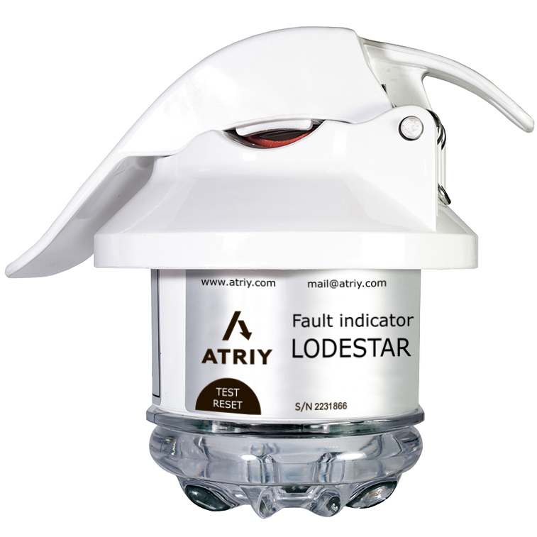
Lodestar CL HVDD
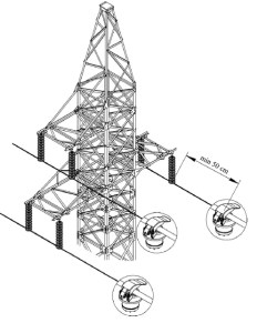
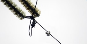
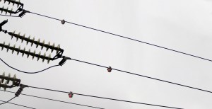
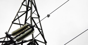
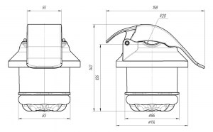
Fault indicators for high-voltage lines
Lodestar CL HVDD detects a faulty event on overhead lines and determines the direction of emergency currents, which shows the maintenance team where the faulty section is located. It is very convenient for use on the border of different energy systems, state borders and before natural barriers (water etc.). It transfers all line parameters via GSM communication directly to the SCADA system, and sends event notifications via SMS and email to the maintenance team’s smartphones. This will help you quickly find the place of damage in hard-to-reach areas.
Lodestar CL HVDD benefits:
• All Lodestar HV indicators are equipped with a short-range radio channel of the Bluetooth Low Energy standard, which allows you to easily configure and adjust the settings from any smartphone with the PPI-3 software installed;
• It is possible to determine the status of the high-voltage line both visually, thanks to the LED indication, and using a portable remote control. (Smartphone with Lodestar App);
• CL HVDD could be easily configured from SCADA system KOMORSAN using communication unit (Smartbox, Lightbox).
Technical specifications
| Specifications | Lodestar HV | Lodestar HV DD |
| Overhead line voltage class | 110 kV | |
| Grid's frequency | 50 Hz | |
| Visual indication | Ultra-bright LEDs Detection range up to 100 m (during the day), up to 500 m (at night) |
|
| Absolute current response threshold | 25 A | 20 A |
| PtG selectivity | - | Determining the direction |
| Voltage monitoring | + | |
| Remote control (for field config) | - | Bluetooth BLE (2,4 GHz) |
| Types of operation control | 100 ms, off | 0-200 ms |
| Setting the Reset Timer | 6, 12, 24, 48 hours | Configurable from 1 h to 8 days |
| Minimum duration of the emergency process | 0,02 s | |
| Resetting the indication | • On restoring • power • By timer • By a magnet |
• On restoring power • By timer • By a magnet • From a portable remote control |
| Changing Settings | 10 DIP switches | • On the short-range radio channel using a portable remote control • Using KOMORSAN software or SCADA (while indicators connected to Lightbox) |
| Integration with SCADA systems | - | While connecting the indicators to the Lightbox, information is exchanged between the KOMORSAN server and the SCADA system via the IEC-104 protocol |
| Power supply | Lithium battery (19 Ah) | |
| Battery life(in standby mode) | 8-10 years | |
| Total indication time | > 2000 h | |
| Time to failure of the indicator | Not less than 60 000 h | |


