")
")
")

")
Lodestar FM-FL
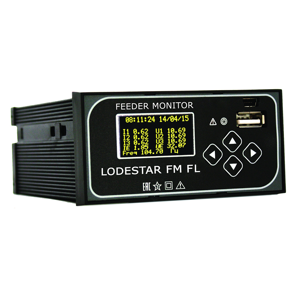
Now it is possible to detect simply the fault localization on overhead, cable and overhead cable power lines with the new universal device Lodestar FM-FL. Such ultra-compact device, mounted easily in the switchgear and control gear cell, monitors the network status constantly and determines the damage location with accuracy of 300 meters. Working in networks with any type of neutral, feeder monitor Lodestar FM-FL records any types of emergency situations on cable and overhead distribution lines:
- phase-to-phase short circuit fault
- phase-to-ground fault
- 2- and 3-phase ground short circuit fault
- indicates the direction of the damage place
- identifies arc intermittent ground faults
- determines the damaged phases and line fault
For cells that are not equipped with their own current sensors, it is recommended to install Lodestar FM-FL with current sensors based on the Rogowski coil, which:
- frees the current transformer from unnecessary load
- no distortion when using a current transformer for measurements
- installed in substations where standard current transformers are not planned, mounted or required.
The intelligent feeder monitor Lodestar FM-FL analyzes a wide range of parameters and displays on-line the characteristics of current, power, voltage, industrial frequency, direction of power flow, as well as minimum and maximum values of flow.
Lodestar FM-FL is available to order in three modifications depending on the voltage class and current sensors:
- Lodestar FM-FL+ voltage class 6-35 kV with Rogovsky coils;
- Lodestar FM-FL voltage class 6-35 kV with current transformer sensors SCTxxx;
- Lodestar FM-FL 110 voltage class 110 kV with current transformer sensors a SCTxxx.
Technical characteristics of Lodestar FM-FL system
| PARAMETER | VALUE |
| For installation in substation in a switchgear and control gear cell of a voltage class | 6-500 kV |
| Fault detection selectivity | Detection of the direction of phase-to-ground fault (PtG, PtP) |
| Types of recorded faults | All types of faults |
| Determining the directions of PtG | Yes |
| Determining the fault site | With an accuracy of ±150 m |
| Current response threshold PtG | from 0,5 A |
| Current response threshold PtP | from 10 A |
| Communication interface | RS-485, Ethernet |
| External measuring sensor | - Rogovsky coil / current transformer sensors SCTxxx (3 pcs.) - Standard / capacitive divider |
| Network frequency | 45 Hz to 65 Hz |
| Visual indication of the fault | - LCD indicator - LED indication |
| The number of last faults stored in the internal memory | 500 |
| The power supply used in the indicator | - backup battery (15 years of standby time ) - power supply from an operating current source with any of the voltages = 220 V, = 110 V or from the mains ~ 220 V or direct current from 24 V to 60 V (± 10%) |
| Fault Indication Reset | - external command - by timer - button on the device |
| Additional features | - change of settings using client software - Software Update - log of registered faults |
| Measurement accuracy | - voltage 1% - current 1% - active, reactive and total power 3% - industrial frequency 1% |
| Fault localization accuracy | ± 300 m |
| GPS time synchronization accuracy | Not worse than 1 μs |
| Sampling frequency when recording of oscillograms | 1 MHz |
| Fault observation time | 0.1 ÷ 10 s |
| Preparing for reactivation | no more than 10 s |
| Installation place | in the switchgear and control gear cell, on the control panel |
| Temperature Range | standard from -40 °C to +70 °C |