")
")
")

")
Lodestar PT3
Description
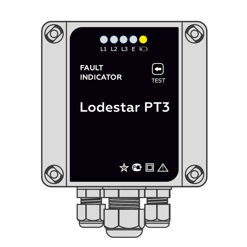
Cable fault locator Lodestar PT3 is intended for detection of fault localization on overhead and cable power distribution lines of 6-35 kV. The fault indicator can operate in networks with insulated and resistance neutral. The cable fault detector is mounted in switchgear and control gear cell on the control board.
Cable fault locator Lodestar PT3 abilities:
- phase-to-phase short-circuits and phase-to-ground faults recording with separation of fault types;
- damaged phase detection;
- transmission of information to dispatching and telemechanics system by means of adjustable relay outputs or RS-485 interface;
- saving up to the last 10 faults in the event log and time tag;
- fault indication by switching on one or several appropriate LEDs;
- the indicator is powered from DC or AC voltage source 220/110 V and 220 V respectively;
- standby power supply of LEDs (at the time of fault indication);
- control of standby battery charge level;
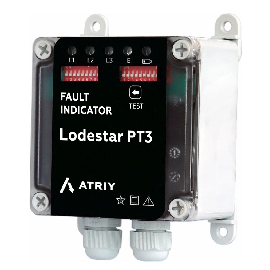
- changing of setpoints by DIP switch and client software.
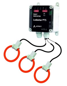
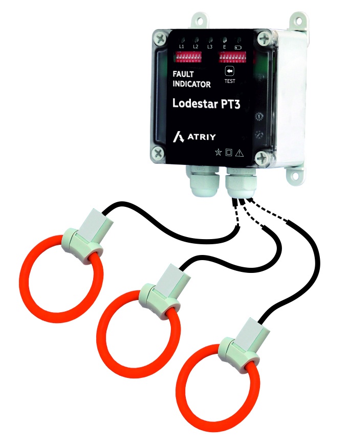
The sensors of Lodestar PT3 fault indicator (based on the Rogowski coil) are mounted directly on cable phase conductors and transmit data to the indicator box. The fault indicator is installed on the board of relay compartment of switchgear and control gear cell.
Cable fault indicator Lodestar PT3 Technical specifications
| PARAMETER | VALUE |
| Events | |
| Types of registered faults | - Identification of 2-phase and 3-phase faults - Identification 2-phase and 3-phase ground faults - Identification of single-phase PtG |
| General description of the cable fault indicator |
|
| Voltage class of overhead and cable power distribution lines |
6-35 kV |
| Visual fault indication | LEDs with high intensity brightness |
| Number of last faults stored in the internal memory | 10 |
| Power supply | Powered from: - an auxiliary services supply with any type of voltage =220 V, = 110 V or from the mains ~ 220 V - standby power supply (lithium battery) for fault indication (LEDs blinking time is more than 900 hours) |
| Fault Indication Reset by | - the external command (by closing of dry contacts (voltage free output relay contacts) - timer - button on the Device |
| Communication | RS-485 MODBUS protocol (in option) |
| Trigger control | - visual - on MODBUS protocols (if the power supply is available) - relay output |
| Mean time between failures | At least 110 000 hours |
| Additional features | - changing of setpoints by DIP switch - RS-485 |
| Parameters | |
| Current response threshold PtG | from 5 A |
| Current response threshold PtP | from 200 A |
| Current threshold range (short-circuits) | 200 ÷ 2000 A |
| Current threshold range (phase-to-ground fault) | 10 ÷ 160 A |
| Fault observation time at phase-to-ground fault | 60 ÷ 300 ms |
| Inrush current response time | 0.02 s |
| Fault observation time at short-circuit | 40 ÷ 300 ms |
| Preparing for reactivation | no more than 30 s |
| Design | |
| Installation place | in switchgear and control gear cell, on the control board |
| Sensors | sensors based on Rogowski coil (3 pcs.) |
| Temperature range | standard from -40°C to +70°C |
| International Protection Marking | IP 65 |
| Impact of external climatic factors | S4 design group according to the requirements and Moderately Cold Climate design of placement category 3.1 according to IEC 721-2-1, but for operation at ambient air temperature from -40 to +70°C |
| Impact of mechanical factors | M7 design according to IEC 721-3-3-87, design group N2 according to the requirements |